Sunday, December 1, 2013

Decision Modeling and Optimization in Game Design, Part 9: Modular Level Design

This article is the ninth in a continuing series on the use of decision modeling and optimization techniques for game design.  The full list of articles includes:


The spreadsheet for this article can be downloaded here: link

We've had to put off this instalment of the series for the last few months, as we've been very busy starting up a brand new game studio in Austin.

We're looking forward to announcing more about that in 2014, but in the meantime, we took advantage of Thanksgiving break to finally write up the long-awaited Part 9 of this series.  We apologize for the delay and hope to get Part 10 completed by January.

The Story of Pirate Planet

It was a warm day in Austin in April of 2007.  As they waited for feedback, the level design team for Pirate Planet on Metroid Prime 3: Corruption grew nervous.  They had been working on building Pirate Planet, one of the game's major worlds, for over five months, but for one reason or another -- due to the inevitable delays and re-prioritizations that always occur in game development -- they had never had a chance to show it to Kensuke Tanabe, their supervisor from Nintendo's Software Planning and Development group.

Now they were only a scant few months from ship, with precious little time for changes, and Tanabe-san -- a man whose frequent and major design changes were almost as legendary as Miyamoto's -- did not seem pleased.

In fact, he seemed rather disappointed.

Instead of offering his usual feedback, he simply said, "Come back tomorrow.  I'll have feedback for you then."

Tanabe-san took a build of the game into his office and shut the door.

When the next day came, the team was stunned.  Tanabe's plan was more than an overhaul -- it was a dramatic redesign.  Every single room was to be connected to a completely different room than before.  The entire world of Pirate Planet was to be completely rearranged, and even many basics such as item pickups were to be moved.

The level design team went through the usual stages that Retro developers experienced when confronted with the often overwhelming feedback from their Nintendo bosses: first, horror at the enormity of the challenge of making so many changes; second, reluctant acquiescence to the fact that they did indeed have to make all the changes listed; and finally, acceptance when they saw the effect of the changes in-game, and realized that nearly all of them were for the better.

The Metroid Prime games benefited enormously from this kind of modular approach to level design, which allowed them to build expensive "rooms" and cheaper "hallways" and separate them with identical doors (which also cleverly masked the loading times as new rooms were streamed in).  This gives designers a great deal of flexibility, then, as it allows them to quickly modify the configuration of an entire level.  Many games use broadly similar approaches, with The Elder Scrolls: Skyrim being a notable and very successful example.

The configuration of the level, then, can be seen simply as a graph.  Each node in the graph is one room, and its connections to other nodes indicate how its various entrances and exits connect to other rooms.

In theory, if we had a formula to tell us whether one graph configuration was "better" than another, we could use that to optimize an entire level, and find the "best" one.

Of course, that's theory.  Naturally, if you're an experienced level designer / world-builder, you know that there are far too many factors that go into consideration when building a level to try to build all of these considerations into any kind of neat mathematical formula or an Excel spreadsheet.  It's an ongoing, iterative process, with countless considerations based on all of the player's possible paths through the space.

But it's useful to take a look at how you would approach this problem in practice to see what can be done and how you can go about doing it, and what the capabilities and limitations of decision modeling techniques are when we apply them to this sort of problem.

And it's useful to know that there's a tool that can answer part of the problem for us, and suggest possibilities, even if we don't end up using decision modeling to figure out how the rooms are connected.

A Sample Problem

Suppose for a moment that our game is based on a reconfigurable room system, just like the Metroid Prime games.  Assume that we have various types of rooms that all fit within a square grid.  We have pre-built rooms that connect 2 neighboring rooms ("L"-shaped or straight line), rooms that connect 3 other rooms ("T"-shaped), and rooms that connect 4 neighbors ("+"-shaped).

We can visualize these as similar to the road tiles in the classic board game Carcassonne (playable on Kongregate here):


Assume we have a fixed "level entry" and "level exit," and we need to figure out the best set of rooms that will connect them.


We can place any of our rooms anywhere inside the grid, and we can rotate them arbitrarily.  Also, for the sake of simplicity, assume that rooms with 2 exits ("hallways") can be arbitrarily bent or un-bent like a garden hose, so that we can switch any such "hallway" piece between straight and L-shaped as needed.

Your problem is as follows: given the entry and exit points marked above, and assuming you have 9 "2-way" rooms, 4 "3-way" rooms, and one "4-way" room, what's a valid way to place all the rooms in the 5x7 grid above such that each room is used exactly once?


Optimizing Connectivity

We'll begin by using the cells in the 5x7 grid as our decision cells.  Each cell will hold either a '0' or a '1' -- a '0' to indicate that there's no room in the cell, and a '1' to indicate the presence of a room.

We also paste '0' and '1' values around the outside of the 5x7 grid to indicate which tiles have rooms.  The grey tiles on the left and right side indicate the level entrance and exit, respectively.


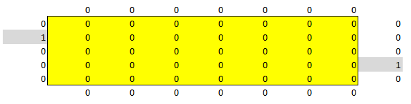
Following the formatting standard we laid out in Part 2, the decision cells are colored yellow to make clear that they are decision variables.

Just below that, we add a second table which counts the number of neighbors of each cell, but only if the cell itself has a nonzero value.  This will be our neighbor count.  More on that in a moment -- we'll show you the completed table after we solve.

Just to the right of that, we add up all of the things we want to happen when we optimize this table.


Each row of this table indicates a constraint.  The "Actual" column determines various things about the actual current characteristics of the decision table or the neighbor count table.  The "Desired" column indicates the value we actually require in each case (i.e. the desired value) as stated in the problem statement above (i.e. the values stated in the previous section, "A Sample Problem").  The "Difference" column just subtracts the "Actual" column from the "Desired" column.

Finally, the "Total Difference" cell will be our objective cell.  This simply adds up all the values in the "Difference" column.  We're trying to minimize that value -- ideally, it should reach 0 to indicate that this problem is "solved."

The first four rows count how many cells of various types exist in the neighbor count table (1-neighbor, 2-neighbor, 3-neighbor, and 4-neighbor cells, respectively), using Excel's COUNTIF() macro.  Finally, the last row counts whether there are tiles right next to the entrance and exit.

What else do we need?

Well, in theory, we also need a way to make sure there's a connection between the entrance and the exit.

The constraints above -- telling the solver that we want 0 1-neighbor tiles, 9 2-neighbor tiles, 4 3-neighbor tiles, and 1 4-neighbor tile -- should ensure that we end up with the right number of tiles and that everything is connected in a way that's valid.

If you think about it, though, it should be clear the guarantee of connectivity does not guarantee that there will be an actual path between the entry and the exit.  It's possible that individual clusters could form near the entry and exit points, or that there could be separate pieces floating off in the corner, not connected to anything else -- for example, you could get 4 "L-shaped" 2-way tiles in a small square, each connected to two others but none of them connected to the rest of the level.

However, we'll put off dealing with this problem -- proving reachability is overkill for this particular problem, when the fact is, it will probably be fine when we solve it, and if it isn't fully connected as we expect, we can just solve it again to get a new answer.

Finally, we run Excel Solver.


Note how simple this is.  We simply set it to minimize the objective cell, then specify the yellow decision cells as the variable cells and add constraints that they must be integers between 0 and 1.  We select the Evolutionary method and press Solve!

Solved!

After running the Evolutionary solver for a while, you may get something that looks like this:


Note that we've enabled the "conditional formatting" feature in Excel to color the second table -- the one that counts the number of neighbors.  As you can see, each cell properly counts how many neighbors it has (if you include the 'entry' and 'exit' cells just outside the table), and there are exactly 9 2-neighbor cells, 4 3-neighbor cells, and one 4-neighbor cells, which is exactly what we wanted.

Problem solved!  With just a tiny amount of work, we've gotten Solver to figure out a whole new level configuration for us based on our specifications.  We can even run Solver several times with different random seed values to see which level configurations it suggests, and from there, figure out which of those configurations seem to work best.

In terms of Carcassonne tiles, our level would look like this:


We can then use Solver to quickly spit out suggestions for alternate room configurations.  For example, if we want to generate a layout with 10 2-neighbor tiles, 6 3-neighbor tiles, and 2 4-neighbor tiles, we could just plug those numbers into our constraint table and re-run Solver to get something like this:


Extending the Example

Now let's say we want to extend the example to include the difficulty level.

Assume that each room has an overall difficulty level that represents how much of a challenge the player will encounter in that room, where '1' represents an easy room, '2' represents a moderately challenging room, and '3' represents a challenge, with a room that contains a boss monster or something like that.  So instead of simply using a '1' in our decision table for each cell with a room in it, we'll have a number between 1 and 3 indicating difficulty.

Our first criterion is that we want some variation in difficulty levels.  So we'll add a new table where each cell measures the change in difficulty between that cell and any nonzero neighboring cells (or 0 if the corresponding cell in the decision table is 0).


Now we add a cell to our constraint table that measures the average difficulty change -- the first row inside the red box in the modified constraint table shown below.  It does this using Excel's AVERAGEIF() function to count the difficulty change from the table above if the corresponding cell in the decision table is nonzero.


The second row in the constraint table tests whether there's one cell in the second-to-last column to the right (column H) with maximum difficulty.  This will help us ensure that the maximum difficulty is close to the exit, since the exit is at the rightmost side.

We also add a third row to check if every column in the neighbor cell is nonzero.  This will return a value of 1 only if each column of the neighbor count table is nonempty.  Since we know that a valid solution must have nonempty columns, this constraint will make it more likely that the generated level is fully connected, and there is a path between the "entry" and "exit" cells.  By itself, it's not enough to absolutely guarantee that the level it generates will be properly connected, but it gives us better odds than the previous spreadsheet did.

Finally, we make sure these three rows are added to the "Total Difference" objective cell, and solve.  Note that the Solver dialog is exactly the same as before, except that we now constrain the decision table cells to have values between 0 and 3 instead of 0 and 1.

Let it run for a few minutes, and voila!


Our decision table looks almost identical to the last one, except that each decision cell has a difficulty level associated with it, and the average difficulty change is 1.

Conclusion

Of course, this is something of a toy problem.  We built a grid-based system simply because that's what we can represent most easily with the grid-based design of Excel, but most component-based level design systems don't lend themselves to this format.

However, with a little work, we could also adapt this to a different, non-orthogonal representation, such as the graph-based representation we used in Part 8.  We could also limit ourselves to swapping compatible rooms within an arbitrary fixed configuration, and use that approach to find the best configuration of rooms within a game level without changing the overall layout.

In any event, the fact that it was so easy for us to build this example should tell us something.  There are clearly a vast number of ways to apply this approach; if we can only find a useful fitness function for the right configuration of rooms, it becomes almost trivial to apply that to many types of level recombination problems.

Stay tuned for Part 10, due sometime in the next few months, when we'll wrap up our discussion of decision modeling and discuss some very important big-picture issues.

-Paul Tozour

This article was edited by Professor Christopher Thomas Ryan, Assistant Professor of Operations Management at the University of Chicago Booth School of Business.

Sunday, September 22, 2013

Decision Modeling and Optimization in Game Design, Part 8: Graph Search

This article is the eighth in a continuing series on the use of decision modeling and optimization techniques for game design.  The full list of articles includes:


The spreadsheet for this article can be downloaded here: link


    Metroid Prime World Design

    If you’ve ever played any of the games in the Metroid Prime trilogy (or for that matter, any of the Metroid games), then you’re familiar with the way a typical Metroid world is set up.  Each map is a complex, interlocking set of rooms, with many parts of the map sealed off by requiring access to different suits, weapons, and power-ups.  As the player gains access to new technologies such as "morph ball mode," "spider ball mode," and different suits and weapons, different parts of the map structure gradually unlock, forcing a large amount of re-traversal for the player to visit each new unlocked area.

    As a result of this complexity, handling all of the traversal and re-traversal opportunities available to the player at each point in time is one of the major game design challenges on a Metroid style of game.  If we move any rooms, change the connections between rooms, or change the location where the player gets a certain suit or weapon or power-up, that has the potential to completely change the player's flow and quite possibly break the game.

    The in-game map looks something like this:


    If you’re a programmer, you’d probably look at a map structure like this and immediately realize the potential for all sorts of design tools you could use to build and manage the map structure.  Most likely, you'd make a system where designers could:
    • chart out a map's structure graphically,
    • get instantaneous feedback on where the player could move at each stage of the game,
    • view the combination of rooms the player could access with any combination of power-ups, and
    • instantly determine the fastest route from any room to any other room with any possible combination of power-ups (or indicate that no such path exists).

    Under the hood, you'd probably use an A* search or Dijkstra's search along the graph, taking the player’s movement capabilities into account while crossing each graph edge.

    A tool like that would be relatively easy to create; it would probably only take a talented programmer a few days to write, and it would likely save designers several weeks over the life of the project.

    Surprisingly, though, the creators of the Metroid Prime series never had a tool like that.  When I worked at Retro Studios / Nintendo between 2003 and 2008, we did it the old-fashioned way, and our then-Assistant Producer meticulously maintained large printed maps of all the worlds of each Metroid Prime game, hanging all of them around the company meeting room.  Each time one of the worlds changed, he would edit the associated map graph and re-print all the affected world maps.  These maps looked a lot like this:


    As much as we'd like to actually create a "map design tool" like this, we promised in Part 1 that we wouldn't write any code in this series.  So that kind of a full-featured map design tool is outside the scope of this article.

    What we'll do instead is show how we can handle a problem like this directly inside Excel.  So even if we're designers who can't get any programmer support to build this kind of a tool, we can still create something similar without having to rely on outside help.  And once we're done, we'll have a good template in place that programmers can take and run with to build exactly that kind of a map design tool.

    The Metroid World Example

    To illustrate this problem, we will build an example "Metroid world" and show how to solve it in Excel.  In order to prove that you can actually handle a problem like this from right inside Excel regardless of complexity, we’re going to make this a very complex problem, with 17 rooms and non-obvious connections between them.

    Our example world will look like this:


    Each bubble shows a different room, and the arrows indicate the connections between pairs of rooms.  The number next to each connection indicates the cost of traversing that connection in either direction.  We'll assume these costs fully account for the traversal time to get between any pair of rooms, and there are no costs associated with the rooms themselves (i.e. the traversal costs are to some arbitrary point inside each room).

    We'll explain the coloring of the different rooms later.

    Once we've built the model, we'll be able to ask it questions such as "what's the shortest path for the player to get from the Library to the Sanctuary?"

    A Simpler Problem

    Let's start by working our way up to that with a simpler problem.  Assume we have 6 rooms, 'A' through 'F', with connections as shown in the following directed graph.


    We want to know: what's the fastest way from A to F?  Is it ABEF, ABCEF, ABCDF, ADF  ...?

    You can quickly figure it out yourself by adding up the weights in all four potential paths, but let's see how we'd encode it in Excel Solver.

    First, we make a column with all the possible arcs: A->B, A->D, B->C, etc.  For each arc, we list the total distance of that arc (its traversal cost) in the "Total Distance" column.  To the right of that, we have columns for each room, and for each arc, we put a '1' in the room where the arc originates and a '-1' in the room where the arc terminates (so, for example, "C->D" has a '1' in the 'C' column and a '-1' in the 'D' column).


    We also have a "Decision Variables" column in yellow -- this indicates which arcs the decision model will actually use.  Right now, we'll set all of those to 0 to indicate that they're not currently used (i.e. the problem hasn't yet been solved).

    Because we're following the formatting conventions listed in Part 2, the decision variables are yellow and the predefined values stated as part of the problem description are in blue.

    Now, we add two rows beneath the right part of the matrix to sum up the current target values: this is the "Current" row shown below.


    The "Target" row indicates what we're attempting to achieve.  We simply put in a '1' for the origin, a '-1' for the destination, and '0' for all the other values.  We will use these when we set up the constraints later in the exercise in order to make sure that any potential solution begins and ends where we want it to.

    Finally, we set up the objective function.  This is simply the decision variables multiplied by the respective values in the "Total Distance" column (implemented with the Excel SUMPRODUCT() formula).  In other words, if any arc is used, its decision variable will be 1, and we will multiply it by the respective length of that arc in the "Total Distance" column; otherwise, its decision variable will be 0, and we will get a 0.  This will ensure that the objective function accurately measures the total distance of all the arcs that are actually used in whatever solution we find.

    Now, we solve (see Part 2 if you need a refresher on how to find and use Excel Solver).


    In our objective ("Set Objective"), we specify the orange objective cell.  Since the objective represents the total distance, and we want to minimize the total distance, we select the "Min" radio button below that.  For our decision cells ("By Changing Variable Cells"), we specify the yellow "Decision Variables" column.  In the constraints section, we specify that the yellow decision cells have to be integers that equal 0 or 1.  We also specify that the "Current" row has to equal the "Target" row, to ensure that the path begins and ends at the correct rooms.

    Before we solve, note that "Select a Solving Method" at the bottom has "GRG Nonlinear" specified instead of the usual "Evolutionary" solver.  We'll have a more detailed discussion of the different solver types in a future episode, but for now, suffice it to say that the GRG Nonlinear solver ("GRG" stands for Generalized Reduced Gradient) sometimes handles problems of this type much better than the Evolutionary solver does.

    Now, we hit Solve, and Solver fills in '1' values for the decision variables associated with A->B, B->C, C->D, and D->F, for a total path cost of 8 (note that Solver may take a few minutes to find this solution).  You can verify by hand that this is the correct answer by adding up all of the path costs of the other possible paths, which are all greater than 8.

    You can find this solution in the "Sample solution" worksheet of the attached spreadsheet.

    Searching in the Metroid World

    With that framework in hand, let's generalize it to the large Metroid sample world above.

    One big change in this version is that this example includes bidirectional links instead of directed arcs between rooms.  This means our decision variables will no longer simply be '0' or '1' to indicate whether an arc forms part of the shortest path; instead, we'll also use '-1' to indicate that the path is traversed backwards.

    [Note that this approach only works because all of the arcs in the Metroid example are bidirectional.  If we had any directional arcs in our example, we would have to use the previous approach, and specify any bidirectional arcs as two separate rows in the spreadsheet (for example, we'd have to specify "Lab -> Oculory" and "Oculory -> Lab" on two separate rows to indicate that the player can move between the two rooms in either direction).]

    Our spreadsheet looks similar to the previous one, except that we now add two columns, "Traversal direction" and "Absolute value of decision variables."  "Traversal direction" is just a visual assistant to indicate which direction we'll traverse a link, with a decision variable value of '1' translated into "Forward" and a value of '-1' translated to "Backward."


    We also change the objective function so that it multiplies the total distance column by the "Absolute value of decision variables" column rather than the decision variables themselves (since traversing a link backwards gives us a '-1' in the "Decision Variables" column, and multiplying this by the distance value would give us a negative distance).

    We also need to change our constraints so that it accepts integers between -1 and 1 in the "Decision Variables" column instead of 0 to 1.

    In the "Target" row below the room source/destination matrix, we enter a '1' for the Library and a '-1' for the Sanctuary to ask Solver to figure out the shortest path from the Library to the Sanctuary.

    After these changes, we solve again.  Note that because this is a much more challenging problem, we now have to tweak the Solver options a bit.  In the Solver dialog, we hit Options, select the GRG Nonlinear tab, and then check "Use Multistart" and set "Population Size" to 20 (see this link for more info).  This will make Solver do a much more exhaustive search and will make it much more likely to find the global optimum, and the expense of taking a bit more time to solve the problem.  With this option set, Solver may take 3-5 minutes to find the correct solution.


    After Solver finds a solution, we scan the "Traversal direction" column to make sense of the solution that Solver came up with.  We get the following as the shortest path:

    Library -> Sanctum -> Plaza -> Starport -> Chapel -> Sanctuary
    ...  for a total cost of 21.

    You can find this setup in the "Metroid world solution" worksheet of the attached spreadsheet.

    Adding Movement Constraints

    Of course, this still doesn't quite give us what we want.  The actual Metroid worlds have complex movement requirements that limit the player's access at any point depending on the exact combination of equipment he has acquired.  What we really want is a way to limit the search to only those rooms that are valid with a given combination of equipment.

    There are a lot of different ways to do this, but for the sake of simplicity, we'll just assume each room in the Metroid world graph above requires one particular type of equipment.  Then we'll solve that problem and leave any more sophisticated implementations as an exercise for the reader.

    We will assume the following colors in the graph have the following meanings:


    • Pink rooms (Library, Ruins, etc) don't require any special equipment.
    • Green rooms (Sanctum, Plaza, etc) require the player to have the morphball technology
    • Blue rooms (Courtyard, Throne Room, etc) require the player to have the Varia suit upgrade
    • Red rooms (Chapel, Furnace, etc) require the player to have access to missiles


    The goal is to use Solver to help us figure out how the optimal path for the player changes depending on whether or not he has the morphball, Varia suit, and/or missiles.

    We'll start by adding an "equipment required" table near the top of the spreadsheet:


    This table uses a '1' for each cell to indicate that the player currently has access to that technology, or a '0' if he doesn't.  So far, we've been assuming that the player can travel anywhere, so we've filled in a '1' for each technology.

    Now, we add two rows directly below the arc matrix, "Room category" and "Multiplier."


    Room category specifies the equipment type of the room listed in the same column -- None ('0'), Morphball ('1'), Varia suit ('2'), or Missiles ('3').

    The Multiplier row contains a formula that checks the room category in each column against the "Equipment required" table above.  It produces a '1' if the player possesses the appropriate equipment, and a '0' otherwise.

    The grey cells below that are a table that combines the arc reachability table above with the "Multiplier" row.  It produces a '1' if the room in the same column is included in the path for the corresponding row, and the multiplier in the same column is 1 (in other words, it multiplies the absolute value from the arc reachability table by the multiplier in the same row).

    We also add an additional column to the table just to the right of the "Total distance" column: "Traversable with current equipment."  This column will produce a '1' if both rooms in the arc are reachable with the player's current equipment.  If not, it will produce a value of '999' in order to make the arc prohibitively expensive.


    Finally, we change our objective cell (the orange cell called "minimum total distance") to also include this column in its SUMPRODUCT() formula.

    Now, we run Solver exactly as before.  Make sure you have the Options set as specified above (Use Multistart = TRUE with a Population Size of at least 20), or you may not get the desired results.

    First, we'll set the value for "Morphball" in the "Equipment required" table at the top of the spreadsheet to 0 and re-solve (note that this may take 3-5 minutes to solve).  This is the optimal path with no morphball:

    Library -> Ruins -> Survey Room -> Courtyard -> Lab -> Oculory -> Chapel -> Sanctuary
    ...  for a total cost of 25.

    Next, we set "Morphall" back to 1 and set the cell below it to 0 to find out the optimal path when the player doesn't have the Varia suit:
    Library -> Sanctum -> Plaza -> Starport -> Chapel -> Sanctuary
    You'll notice that this is exactly the same as the solution we found in the previous worksheet, before we began taking the player's equipment into account.

    What happens when we set both of these to 0, so the player doesn't have the morphball or the Varia suit?  Re-solving, we get:
    Library -> Ruins -> Foyer -> Mausoleum -> Sanctuary

    for a total cost of 41.  As you can see from the graph above, going down the very expensive Foyer -> Mausoleum arc (with a cost of 27) is the only option available when both the morphball (green) and Varia suit (blue) are disabled  ... and this is, in fact, the shortest path that includes that link.

    Problem solved!

    You can find this spreadsheet in the "With equipment requirements" worksheet of the attached spreadsheet.


    Conclusion

    In this example, we've shown how you can use decision modeling and optimization techniques as a powerful tool to solve graph search and reachability problems.  This particular Metroid game world example is of course only one application of this technique; there are many more.  You could just as easily use it to find the shortest path through a star system in a space game with direct links between stars, for example, or the shortest path along a flight path network in an MMO such as World of WarCraft.

    Tune in next time, when we'll show how you can use decision modeling and optimization techniques to not only search through game world configurations, but to help design those configurations in the first place.


    -Paul Tozour

    This article was edited by Professor Christopher Thomas Ryan, Assistant Professor of Operations Management at the University of Chicago Booth School of Business.

    Sunday, September 8, 2013

    Decision Modeling and Optimization in Game Design, Part 7: Production Queues

    This article is the seventh in a continuing series on the use of decision modeling and optimization techniques for game design.  The full list of articles includes:


    The spreadsheet for this article can be downloaded here: link

    Introduction

    In the previous articles in this series, we introduced the concepts behind decision modeling and optimization and showed how they can be useful in framing and solving a surprising number of design decisions.  We also discussed many of the limitations of these techniques.

    In this post, we'll show how these techniques can be used to optimize an undeniably hard design problem.  So, hang on to your hats: this example is going to be a beast.

    Once we're done, though, it should be very clear how this approach can be useful for tackling some very difficult design problems that can't reasonably be solved any other way.  Although it's a bit of work to set it up, the spreadsheet we end up with will serve as indisputable proof that decision models can answer some questions that are difficult or impossible to solve any other way.

    Our example is based on a production queue for a colony in a classic "4X" strategy game.  As designers, we want to know: what's the best order to build things in our colony?

    This will give us all sorts of insights into whether there is a "dominant strategy" that allows players to most easily win the game, or whether there are problems with the balancing of our game's buildings or the game rules.

    If we were to have some sort of system that allowed us to automatically see the best production queue for a given city or colony, that would be fantastically useful, wouldn't it?  Then we could tinker with the costs and benefits of each building, or experiment with our game rules, and see how the optimal production queue changed.

    In this installment, we're going to show you how to build exactly that kind of system.

    Although this example is limited by a simplified game model and the limitations of Excel and Excel Solver, it should be clear to anyone with a programming background how you could easily extrapolate from this example to your own model in a high-level language such as C++, C#, or Java, and potentially integrate it with your own game as well.

    Master of Orion

    In 1993, a small studio in Texas released a brilliant classic "4X" strategy game called Master of Orion.  Three years later, they followed it up with another classic, Master of Orion II: Battle at Antares.  These games were two of the initial forerunners in the space-based "4X" strategy genre, and laid the groundwork for later franchises such as Stardock's successful Galactic Civilizations series.  Our example in this case will use colony in a game broadly similar to Master of Orion II.


    A colony in MoO 2 is essentially identical to a city in a typical '4X' strategy game such as Civilization.  It serves as a growing population center, and the player can build one building at a time in the colony to increase its capabilities.


    Let's say you're designing a new game in the style of MoO 2.  You want to know what the optimal initial build order is in the general case -- that is, all things being equal, what's the best sequence of actions for a player to build up a colony?

    Being able to answer this question will be enormously useful to us in helping to balance the game and design all of the different building types.

    Your population begins at 1 million people.  It has a defined "maximum population" of 10 million people.  It grows at a rate that depends on the ratio of the current population to the maximum population:

    • At 10% of maximum population or less, it grows at 2.5% of the current population each turn
    • At 20% of maximum population size, it grows at 3% of the current population each turn
    • At 30% of maximum population size, it grows at 3.5% of the current population each turn
    • At 40% of maximum population size, it grows at 4% of the current population each turn
    • At 50% of maximum population size, it grows at 4.5% of the current population each turn
    • At 60% of maximum population size, it grows at 4% of the current population each turn
    • At 70% of maximum population size, it grows at 3.5% of the current population each turn
    • At 80% of maximum population size, it grows at 3% of the current population each turn
    • At 90% of maximum population size, it grows at 2.5% of the current population each turn
    Also assume that the population is divided into "citizens," with each "citizen" representing 1 million people (rounded down).  Each citizen requires 1 unit of "food."  Each citizen can be dedicated to either farming or production.  Each citizen designated as a farmer will grow 3 units of food, and the colony will automatically allocate as many farmers as needed to growing enough food to ensure all citizens are fed, with the remaining citizens dedicated to production (i.e. they are "workers").

    Also assume that a colony produces 1 unit of "production," plus 2 additional units for each citizen designated as a "worker."

    There are 5 initial building types in a colony:

    • A Hydroponic Farm generates 2 additional food every turn.  It costs 32 production units to build.
    • The Biospheres improvement increases maximum population size by 3.  It costs 56 production units to build.
    • The Cloning Center improvement adds 100,000 additional population every turn.  It costs 36 production units to build.
    • The Factory increases the production of each worker citizen by 1.  It costs 44 production units to build.
    • The Robotic Factory adds a flat 5 production units plus an additional 1 production per worker.  It costs 56 production units to build.
    Additionally, there is a sixth thing we can build: Housing.  We can build "Housing" whenever we like; unlike the others, it is not a discrete "building" but a target for us to allocate resources toward.  Every turn that we build Housing, we generate an additional 10,000 population per unit of production.

    This setup is a bit simplified compared to Master of Orion 2, but it's rich enough to prove the point we need to make here.

    Our question is: given the above, what should the player build, and when should he build it, in order to get to the best possible colony as quickly as possible?

    This is an even trickier problem than it first appears.  If it were simply a matter of finding the best ordering of a Hydroponic Farm, Biospheres, Cloning Center, etc, to build then we could just look through all 5!=120 combinations.

    But in fact, the player can build Housing on any turn, and this has a huge effect on the colony's population.

    So we're left with a much more complicated question: which of the 6 things (5 building types or Housing) should the player build for each of the N turns until all the buildings have been completed?


    The Simulation

    To solve this, we'll build a model conceptually similar to the one we used to solve for the tax rate in Part 2 of this series: we'll put the starting stats for the colony at the top of the attached spreadsheet and then show each new turn of the game on a subsequent row.  You can think of this as "unrolling" the game simulation onto the spreadsheet, with the vertical axis representing time.

    We'll start by making a table of "Production ID numbers."  These are fixed numerical IDs we'll use to refer to each of the five building types, plus Housing.  For example, '2' means "Biospheres."  We'll show why this is useful in a moment.


    Since we're carefully following the formatting standards we laid out in Part 2, these cells are all blue, indicating that they're fixed values that are part of the problem definition.

    Next, we'll set up a table for the population growth rates we described earlier:


    We'll also put in a table with some of the constants we described for the colony in the previous section.


    Now that we have these tables in place, let's build the simulation.


    We start by modeling population growth.  This part of the spreadsheet lists the turns along the leftmost column, and in the subsequent columns, it lists the current population (in thousands), the number of "citizens" (population in millions), the current population maximum, the ratio of current to maximum population.  Then, the "Growth Rate Next Turn" column looks up the current growth rate value in the "Growth table" above, while the "Growth Next Turn" multiplies this factor by the current population (since the growth rate is in terms of a percentage of current population).

    You'll notice, however, that this is actually 35 instead of 25 for the first two turns.  This is because we're actually building Housing for now, which adds another 10k population a turn.  We'll get to that part of the spreadsheet in a moment.

    "Population (in thousands)" grows every turn by adding the previous population to the "Growth Next Turn."  So, the 1000 population on turn 0 becomes 1000+35=1035 on turn 1, and so on.

    Next, we'll model the citizens' job roles:


    We know that each farmer produces 1 "unit" of food.  In this part of the spreadsheet, we determine the number of farmers and workers each turn.  Each new "citizen" added to the city will become a worker by default.  Any time the colony's food demand (= number of "citizens") exceeds the current food production (=3 x number of farmers), we'll reallocate one of these workers to a farming role instead.  The production column lists current production according to the formulas stated at the top (1 unit of production + 2 per worker, plus any modifiers based on whether we've built things like a Factory or a Robotic Factory).

    Now, we model the 5 different buildings.  For each building, we simply list the "production units" required to construct it in the top row.  In each subsequent turn, the production units will decrease if we're working toward that building.  If the value in any of these columns becomes 0 in later turns, it indicates that the building has been completed successfully.


    This gives us an easy way to track both the status of any building (whether it's been created or not), and our progress toward completing each of them.

    Finally, in the rightmost column, we put in our decision cells.  These cells will be integers that express our production decision for what to build each turn.  Because we're following the formatting conventions laid out in Part 2, these cells are yellow, because they're the ones we're going to tweak with Solver.


    The formulas in the spreadsheet are a bit too complex to go into in detail here; the reader is invited to download the attached spreadsheet.  However, the important thing to note is that as we change the cells in this column to any value from 1 through 5 (the Production ID Numbers we listed in the table above), the spreadsheet allocates all our production resources that turn toward any of the five different buildings in the "Production Remaining" column (download the spreadsheet and tinker with the values in this column to see for yourself).  If we keep them at 0, it represents Housing, and it adds to the colony's population instead.

    Optimizing

    There's still one thing we're missing: an objective function to help guide Excel Solver to the right answer.

    Our objective function should be something that expresses how powerful our city is -- its total population and the sum of all its capabilities.  A highly skilled, "min-maxing" player will want to build the colony to its maximum capability level -- that is, maximum population, food production, and production output -- so that it can make the greatest possible contribution to the player's space empire.

    Moreover, such a player will also want to achieve the maximum level of food and production output as early as possible, so that if the colony is interrupted by the need to do something else before this initial production queue is completed -- for example, it's attacked by an alien race and needs to retarget to military production -- it's likely to have a higher production capability at such a point to help it best address that challenge.

    In other words, even though the blue curve and the red curve in the illustration below both get to the same endpoint of total production capability over time, we should prefer the red curve because it gets us to a higher level of total production capability earlier than the blue curve does.  So we care about the total area under the curve, not just the endpoint of the curve.


    We'll build this as a customized function by adding three different values together:
    • The total food production throughout all turns of the simulation.  It might be enough for us to simply take the total value of food production on the last turn, but that might not differentiate between scenarios where we ramped up to maximum food production earlier in the simulation and those where we only ramped up later.  All things being equal, we want to get to maximum food production as early as possible, so we'll take the sum of the food production over all turns.
    • The total production over all turns.  Just as with food production, it makes the most sense to add the sum of production over all turns to reward earlier production gains.
    • An additional penalty for any buildings left unfinished.  We want to ensure that all 5 building types are completed by the end, so we'll take the sum of all the remaining production units required on all 5 buildings and subtract it from the total.  This should also help Solver find the best solutions more easily, since buildings don't have any effect on food or production until they're completed, and this factor helps reward Solver for partially completing buildings, whereas the previous two elements did not.
    We then add those three values together, and we now have the following at the bottom of the spreadsheet.


    Now that we've set up the spreadsheet, running Solver is surprisingly easy (again, if you're unfamiliar with Solver or can't find it in your copy of Excel, see Part 2).  This simply sets the orange "total score" cell above as the optimization objective, tells Solver to try to maximize its value, and sets the decision cells to the entire row of yellow cells in the "Work on what?" column.  It also tells Solver that these need to be integers between 0 and 5 (matching the 6 different values listed as our Production IDs in the table above).


    Now, we hit Solve.


    Not So Good  ...

    When you run Solver, you'll notice that it takes quite a long time to solve.  Since it's using the Evolutionary solving method (the drop-down box at the bottom of the dialog shown above), it can take a very long time to experiment with lots of different possible solutions and try to evolve the best solution.

    In our first run, we get a total of 593 for our objective function after 64 turns of game time.  This isn't very good; only the Hydroponic Farm and the Robotic Factory have been built.  Repeated attempts to re-optimize don't seem to improve the solution at all.

    The real problem here is that there are just too many parameters to optimize.  We've asked Solver to solve 64 different parameters; there are a massive number of possible solutions.  We've given Solver too big a haystack and too small a needle.

    If you wanted to throw money at the problem, you could probably fix it by licensing a more powerful Solver engine from the folks who make Excel Solver.

    But of course, that's not the approach I would recommend!  There are inefficiencies in our decision model setup, and it would be far better for us to fix those first and see if fixing them won't let Solver find a solution.

    As anyone who's done AI pathfinding knows, the best way to optimize your pathfinding algorithm usually isn't to tweak the algorithm itself, it's to simplify the space that it needs to search on.  The simpler and coarser the pathfinding representation, the more quickly any search algorithm will run.

    So we need to do the same thing: we need to take our 64 individual "What should I build this turn?" decisions and transform them into a much smaller set of decisions that Solver can handle using some kind of dimensionality reduction.


    It Only *Looks* More Complicated ...

    Let's rephrase our question.  We can take advantage of the fact that any time we start building a particular building, we'll want to keep building it until we're finished.  It seems safe to assume that the optimal production queue will build each of the five buildings in a focused stretch until they are done -- that is, there's nothing to be gained from stopping production on a building before it's finished to work on something else.

    This assumption allows us to rephrase the question from "What should I build every single turn?" to a much simpler series of questions:

    • How many turns should I build Housing before I create the first building?  (0 or more)
    • Which building should I build first?  (Production ID 1 through 5)
    • How many turns should I build Housing between the first and second buildings?  (0 or more)
    • Which building should I build second?  (Production ID 1 through 5)
    • How many turns should I build Housing between the second and third buildings?  (0 or more)
    • Which building should I build third?  (Production ID 1 through 5)
    • Etc  ...
    Then we continue that pattern until all 5 buildings have been built.

    In order to do this, we first implement a table above the spreadsheet that looks like this:


    The yellow decision cells on the left are the various "How many turns of housing?" questions we will ask Solver.

    The yellow decision cells on the right are the five production IDs of the five different buildings.

    In the center, we have our production table, which lists the sequence of events -- in this example, 18 turns of Housing, followed by building #3 (Cloning Center), then 1 more turn of Housing, then building #5 (Robotic Factory), then 0 turns of Housing, then building #1 (Hydroponic Farm), etc.

    Finally, in order to implement this change, we take the entire spreadsheet and copy it to a new worksheet in Excel.  Then, we replace all the cells in the "Work on what?" column with formulas that essentially express the build order as explained in the previous paragraph.  This will cause the Production table above to essentially "program" the build order.  We also change these cells from yellow to grey since they are no longer the decision cells.

    The exact formula is very complicated, and I don't want to derail the article by going into all the minutiae of how it's expressed in Excel, but as always, you're welcome to download the spreadsheet and check it out for yourself if you're curious.  (In short, we break it out into two separate columns, "Turns of housing in a row" that lists how many turns remain to build housing, and "Index in production table" that increments as we go further down the production table.  The "Work on what?" column returns 0 (Housing) for even-numbered rows in the Production Table, and returns the corresponding Production ID for odd-numbered rows.)

    We also have to change all of our Solver settings.  The dialog now looks like this:


    Here, the decision cells ("By Changing Variable Cells") are the yellow cells at the left and right sides of the new Production Table we showed above ("Turns of Housing" and "Production ordering").  The constraints simply state that the "Turns of Housing" cells need to be integers between 0 and 40, and the "Production ordering" values need to be integers between 1 and 5.

    [If you've been reading this series diligently, you may be surprised at what's missing in this step.  After all, the Production ordering table on the right side lists cells for the 5 buildings to create, each specified by a Production ID value from 1 to 5.  Don't we need to add some sort of special constraint here to ensure that they end up with unique values, and that we don't cause Solver to try to build the same buildings twice?

    The answer is no  ...  or at least, probably not.  The objective function we've specified above should already reward Solver for building all the building types, and it won't benefit from trying to build a building more than once, so that should already naturally ensure that they're unique.  So we'll leave off implementing this constraint until we actually need it (and as you'll see, we never will, so we can forget about it).]


    Conclusion

    Now, we can run Solver again, and in just a few minutes, Solver should give us our final answer, with our objective function having a value of 884 (if Solver doesn't reach this value for you, try re-running the Solver; you may also need to mess with the Solver's evolutionary optimization settings to help it attain this value).

    This solution represents the following:


    • Build Housing for 10 turns.
    • Then build a Cloning Center.
    • Then build a Robotic Factory.
    • Then build a Factory.
    • Then build a Hydroponic Farm
    • Finally, build Biospheres.
    That's it!

    In a relatively short time frame, we've solved a problem that it would be extremely difficult to solve with guesswork or with any number of testers, and we've gained useful design insights in the process.

    Not only that, we now have a tool that can allow us to quickly see how future design changes will affect the optimal build order.  If we decide at some point down the road to lower the cost of Biospheres from 56 to 40, or change Hydroponic Farms to generate +3 food instead of +2, we can make that change and re-optimize the model to see how it changes the optimal initial build order.

    From here, it's well worth looking at whether Cloning Centers and Robotic Factories are too powerful, too cheap, or too useful, or whether Hydroponic Farms and Biospheres might be too weak or too expensive.  It might be a good idea to play around with the benefits and the production costs of each of these buildings and find the exact point at which Solver changes its answer.  If we could find the point where Solver changed its mind about the ordering of two buildings, that would mean that we'd found the crossover point of those two buildings along a cost/benefit curve.

    Ideally, we'd like to build a tool that would give us an instant sensitivity analysis illustrating how the value of each building changed as its cost (or any other parameter) changed -- though that's a topic for another day.

    It's also worth noting that the buildings in this example lend themselves to a fairly well-defined objective function.  This won't necessarily be the case in general, as many buildings could have more ambiguous or context-sensitive contributions to a colony's success.  For example, the Marine Barracks in the example above generates marines to help with ground defense in case the planet is invaded.  The value of a Marine Barracks will scale depending on the planet's likelihood of getting invaded, and it will naturally be much more useful closer to the empire's borders than it will be in a backwater planet in the farthest sectors of the map where enemies can't reach -- there's no point wasting resources on building defenses for a planet that will never be invaded.

    It also depends to a certain extent on how many turns have elapsed in the game itself, since there is unlikely to be much planetary invasion in the early game, while space empires are just developing, whereas later in the game, enemies become much more aggressive and their technologies allow them to invade more distant planets.

    In these cases, we're left to improvise when determining how such a building would contribute to the production queue's objective function.  In the case of a Marine Barracks, we might have a contribution to the objective function that scales over time, or we might model multiple classes of colonies with different defensive needs (say, Low, Medium, and High), and give Marine Barracks and other such defensive buildings fixed weightings in each case, and see how the optimal production queue changes in each scenario.

    Stay tuned! In future articles, we'll build decision models to help us design game levels, analyze game world layouts in a Metroid Prime style of game, and much more.


    -Paul Tozour


    This article was edited by Rob Zubek of SomaSim Games and Professor Christopher Thomas Ryan, Assistant Professor of Operations Management at the University of Chicago Booth School of Business.

    Sunday, August 25, 2013

    Decision Modeling and Optimization in Game Design, Part 6: Parametric Design Techniques

    This article is the sixth in a continuing series on the use of decision modeling and optimization techniques for game design.  The full list of articles includes:


    The spreadsheet for this article can be downloaded here: link

    Introduction

    In the previous articles in this series, we introduced the concepts behind decision modeling and optimization and explained how they can be helpful in framing and optimizing a surprising number of design decisions.

    We also discussed their limitations, and we showed a number of examples of how they can be used to find optimal player strategies in certain cases and to help optimize design decisions directly (see links above).

    In this installment, we're going to slow down a bit, and simplify.

    We're also going to get much more practical, and how how you can use a very simple decision model to frame certain kinds of parametric design problems.  We'll also discuss the broader practical applications of this approach, including how we used this approach in our recent iOS/Android strategy game, City Conquest.


    Designing Towers


    Imagine for a moment that you want to design a tower defense game.  You know that you have enough production resources available to create 8 unique towers.  How do you go about framing the problem and deciding the best set of 8 towers to include in your game?

    Obviously, you could just go and come up with a bunch of ideas for towers, and then just pick the best out of that group.  That's a start.

    Or maybe you could look at some existing tower defense games, like FieldRunners and Kingdom Rush or any of the popular tower defense mods for StarCraft 2, and then experiment with variations on the towers in those kinds of games.

    But that's not a very disciplined approach, is it?

    If we're just coming up with random ideas, how do we know we haven't randomly chosen a lot of bad ones, or that we couldn't have randomly chosen a bunch of better ones?

    When we design our towers, how do we give ourselves some sort of disciplined basis for deciding that one tower design is better than another?  And how do we know that once we've got our set of 8 towers, that the configuration we've chosen is the best set of 8 towers for our game?  Is that even possible?

    For that to happen, we'd have to invent some definition of "best" in terms of how appropriate they are for our game, how interesting they are, and how well they suit our design goals.

    Obviously, that's a bit of a stretch.  That kind of definition of "best" isn't going to be something we can encode in any sort of function.  And there's obviously no way to have a spreadsheet pick out how "interesting" something is; that's a judgement call and we'll have to do it ourselves.

    Let's take a step back.

    In an ideal world, our process for picking the towers should probably look something like this:

    • First, we'd explicitly specify our design goals.  We'd write down on a sheet of paper exactly what we're trying to accomplish with the design of our towers.  This forces us to clarify our thoughts about the design up front so that we don't go rushing into the tower design problem recklessly and have the bigger picture in mind.
    • Then, we'd set up some sort of framework for making the tower design decision, so that we're designing the full set of towers as an organic whole rather than taking a bunch of towers that were designed separately and throwing them all together.

    Our design goals could include things like uniqueness (every tower should be significantly different from all the others and should play a unique tactical role), usefulness (there should be some situations where each tower is the most useful), and balance (every tower should be appropriately powerful and should have a cost appropriate for its utility).

    (You can find a partial list of my own design goals for my recent iOS/Android game City Conquest in the February 2012 interview on AiGameDev).

    So, let's assume we've done that, and we have our goals clearly defined on an 8.5"x11" piece of paper.  How do we then define a framework for the design decision?


    Design Parameters


    If you look at tower defense games that have a large number of tower types, such as the excellent Element Tower Defense mod for StarCraft 2, or if you look at a large number of tower designs across a broad selection of tower defense games, you'll notice a clear pattern.  All of these tower designs seem to be based on a combination of parameters: they have some method of applying damage, and apply some number of effects, such as damage or healing or slowing.

    This is very similar to the way I approached the design of the towers in City Conquest.  Even though City Conquest is more of a tower defense / real-time strategy hybrid, the tower design is similar enough to a tower defense game that it's worth considering.

    The image below shows some of the different towers available in the game.  The full set of towers was designed together, as a whole, by matching different attack mechanisms with different effects as we describe in this article, in order to ensure that they were as unique as possible and satisfied our design goals.

    For example, along the top row of the image, we have the Chiller Unit (upper-left, which emanates slowing in a radius around itself), the Laser (which fires slowly and damages units in a long, straight line), the Grenade Tosser (which lobs ground-to-ground projectiles that do wide area damage on impact), the Gun Turret (which fires rapid plasma bursts at air and ground targets), and the Missile Launcher (which fires homing missiles at air and ground targets and does a small amount of radial area damage in addition to its direct damage).


    Each tower can be viewed as having two fundamental parameter types:
    • A mechanism of action.  This defines the way the tower applies its effect to the enemy units (or, in some cases, to friendly units or to other nearby towers).
    • An effect.  This is what the tower actually does, and what sort of damage or healing or anything else that it actually applies.
    Mechanisms could include things like the following:
    • Instantaneous shot
    • Ground-to-ground projectile
    • Ground-to-air projectile
    • Homing projectile (can target both air and ground; seeks to target)
    • Circular blast around tower
    • Electric arc (hits multiple nearby units in sequence)
    • Conical spray
    • Linear beam (fires over any number of tiles in sequence along a straight line)
    Effects can include things like:
    • Fast direct damage (i.e. rapid fire against a single unit)
    • Slow direct damage (i.e. heavy fire against a single unit with a long cycle time)
    • Direct damage + area-of-effect (AoE) splash (i.e. damage against a single unit with a small amount of splash damage against other units nearby)
    • Area of effect (AoE) damage only (shockwave)
    • Slow: slows affected enemy units for a short period of time
    • Stun: stops affected enemy units for a short period of time
    • Weaken/debuff: weakens affected enemy units for a short period of time so that they take more damage from all sources while affected by the "debuff"
    • Absorb health: absorb some of the unit's health and apply it to this tower
    • Remove buffs: remove any special "buffs" from the affected unit, such as any speed or health or damage enhancements
    • Push back: push the unit backward a short distance

    (This is only a partial list, of course; we could have any number of "effects," such as turning units invisible, turning them into zombies, or what have you.  This list is only for the sake of the example and the reader is invited to make up his or her own list as needed.)

    We should be able to define our towers as a combination of one mechanism and one or more effects.

    If we do this, the question then becomes, which towers get which mechanisms and which effects?

    Once we answer that question, we'll know each tower's role in the game, and this defines its personality, and we can then use that to determine the tower's visual style and start working on concept art.

    We have 8 mechanism types, and 10 effects.  So each tower will have one of the 8 mechanisms and one of the 10 effects, but 2 of the effects will go unused.  That's fine.

    Of course, there are lots of other ways we could do this, such as by giving each tower multiple effects or allowing it to change mechanisms or effects over time, but for the sake of brevity we'll leave those as an exercise for the reader.


    Applications

    Of course, the point of the article isn't about tower defense games; it's about modeling decisions.  These are all sorts of situations in game design where we need to design a large number of entities in particular functional roles.  For example:

    • Designing buildings or units in a strategy game
    • Designing guns, vehicles, or enemies in a first-person shooter
    • Designing creatures and character classes in a MOBA (multiplayer online battle arena) action game
    • Designing spells, enemies, character classes, or loot in a role-playing game

    Many games already openly embrace parametric design.  Gearbox Software's Borderlands famously embraced parametric design for its weapons, boasting over 17,500,000 different varieties of weapons due to  the ability to create new guns based on different parameter combinations.  A recent Gamasutra article on the evolutionary system behind Team Blockhead Wars described a similar approach based on 10 parameters for each weapon.

    Some might criticize this approach as "slot machine design."  There's some truth to this criticism; this kind of process can easily result in unit/enemy/tower/spell designs that feel rote and formulaic if we're not careful.

    But this is not a fundamental problem with the approach itself.  This approach is only a tool, and like any design tool, it has to be used with caution in the context of the broader design to ensure that the parametric design never has a negative impact on the player experience.

    In particular, we have to avoid falling into the cognitive trap of assuming that quantity equals quality, or that it necessarily even contributes to quality.  Any number of interesting choices we present the player will always provide a better experience than an infinite number of boring choices.


    Tower Design Problem: Setup

    Just as with previous articles, we're now going to show you how to model this problem in Excel as a decision model and then use Solver to optimize it.  Unlike the previous articles, though, this article shows what's essentially a subjective design process, where the numbers represent our own opinions as designers.

    We'll start by simply making a table.  We'll enumerate the towers' possible "mechanisms" along the horizontal axis and the "effects" along the vertical axis.  This is the "Decision Table."

    Then, just above that, we make a row of cells: the "Decision Cells."  Since each of the 8 mechanisms has to be mapped to exactly one effect, we only need these 8 decision cells.


    We're going to ask Excel Solver to fill in each of these decision cells with a value from 0 to 9 (inclusive) to represent which of the 10 effects they're mapped to.  Since they're the decision variables, we've also highlighted them in yellow, as per our formatting standards from Part 2.

    The grey cells in the Decision Table below that simply show a '1' value if the corresponding decision cell (the yellow cell in the same column) equals its row index, or a '0' otherwise.  You can see above that the decision cell values "1 2 3 4 5 ..." result in a down-sweeping diagonal of '1' values.

    [At this point, you may be a bit incredulous.  How can we really set up a table to solve this problem?  After all, if there are 8 tower mechanisms and 10 effects in our list, there's a huge number of possible permutations -- if each tower is assigned one unique effect, that's around 1.8 million possible combinations.  Surely we can't search through all of those and find the best one?

    But of course, we're not going to do that.  We're just going to use Solver to help us make this decision.  All we really need to do is find the first combination that looks good.  If we don't like what Solver gives us, we can ask it to give us another one.]

    Back to the spreadsheet: we now create a second table with a set of weights.  This table will list our own subjective preferences for any given combination of a tower's  mechanism and effect.


    We initially fill this table in with '1' values for anything.  As we design our towers, we'll work by changing the values in this table.  A '1' means that the given combination is acceptable and a '0' indicates that it's forbidden for some reason.

    For example, we might decide that a particular combination just doesn't make sense, or doesn't satisfy our design goals, so we'd set the weight for that combination to 0.  We might also decide to use this to ensure that our game is too similar to another game -- for example, "Instantaneous Shot + Fast Direct Damage" is too similar to the machine gun tower from FieldRunners, while "Homing Projectile + Slow Direct Damage" is too similar to that game's rocket launcher, so we might set those values to 0.

    In the same way, if we've already made up our mind that a certain mechanism/effect combination should be in the game, we can fill in a '1' in that cell and a '0' in all other cells in the same row and column.  This will force the Solver to exclude any other towers from using that same mechanism or effect.

    We can also use this table to specify preferences.  A value between 0 and 1 will indicate that the combination is less desirable than another combination, while a value greater than 1 can indicate that it's more desirable to whatever degree.  (You could also think of these as representing relative utilities in utility theory).

    Finally, we make a third table that combines the Decision Table with the Weight Table.  This is the Combined Output Table, shown below.


    Each of the cells in the Combined Output Table multiplies the corresponding cell in the Decision Table against the corresponding cell in the Weight Table, so that if either of the two values is 0, the resulting value is 0 in the Combined Output Table.

    Also, you'll note the columns along the right side of the table, labeled 'Min,' 'Used,' and 'Max.'  The 'Used' column (in grey) count the number of nonzero entries in the corresponding row and column in the table, and 'Min' and 'Max' allow you to set what the minimum and maximum values should be for those values.

    Note in particular the implementation of the "Used" column.  Since we can use non-integer weights in the Weights Table, we don't want to use the "=SUM()" formula for this.  Instead, we use Excel's "=COUNTIF(range,">0")" for this in order to count the number of nonzero weights, not sum them up.

    In the lower right corner is the objective function.  This cell just sums up the total value of the entire Combined Output Table, and as such, it represents our current preferences in the Weights table multiplied by our design decisions from the Decision Table.  We will ask Solver to maximize the value of this cell.


    Tower Design Problem: Solving

    Broadly speaking, there are two ways we could approach this problem:

    • Try to set the correct weights for every single weight in the Weights Table, and then attempt to solve.
    • Set every weight in the Weights Table to 1, run Solver, and then adjust the weights only when we don't like the solution.

    Either approach is valid.  However, we're going to take the latter approach because it's quicker.  The former approach forces us to figure out a weight for every possible (mechanism, effect) combination,

    Our process will look like this:
    1. Set up all the weight values in the Weights Table with weighting values we think are appropriate.
    2. Run Solver.
    3. Take a look at Solver's solution and figure out if we like the solution it gives us.
    4. If not, go through all the tower combinations we don't like, set the corresponding weights for those combinations in the Weights Table to 0, and return to step 2.

    This might take a little time.  It might be 5-10 run-throughs before we find a combination that we like.  That shouldn't take long, though; the hard part is just getting the spreadsheet and Solver set up.  Once we do that, actually running it and tweaking the Weights Table will only take a few seconds.

    For our initial setup, we have the following, the same as shown above:


    The value of the Objective cell is 8, which is the total value of all the green cells (note that we use Excel's conditional formatting here to color the cells inside this table according to their values and make the table easier to read).

    This result is suggesting we should have an instantaneous-shot weapon that does slow direct damage  ...  a ground-to-ground projectile that does direct damage plus an area-of-effect ("AoE") splash  ...  a ground-to-air projectile that does AoE damage only  ...  and so on.

    Some of these tower designs make sense, but three of them seem a bit silly.
    • The ground-to-air projectile that does AoE damage only is probably a bad idea.  This will be the only solely anti-air tower, and we probably want it to do some kind of direct damage so that it can be useful against individual flying enemies.
    • The homing projectile with the slow effect is also probably a bad idea.  We'll probably want more enemies to be affected by the slowing effect than what we'd get with a homing projectile.
    • The linear beam that removes buffs also seems pretty silly.  This seems like a giant laser weapon that can fire through long groups of tiles at a time, so we probably want that to do direct damage of some sort.
    Since we don't like these three tower configurations, we'll set the weights for these to 0 in the Weights Table and run Solver.

    (If you can't find Solver or you don't have it installed in your copy of Excel, see the instructions in Part 2 of this series.)

    Here's what our Solver configuration looks like:


    The decision cells ("By Changing Variable Cells") are the row of yellow Decision Cells just above the Decision Table.  The other constraints in the Solver dialog simply indicate that the decision cells are integer values between 0 and 9 (to represent the 10 possible effects that they can map to), and that all the constraints on the right side of the Combined Output Table need to apply (that is, the values in the "Used" column need to be greater than or equal to the corresponding "Min" values and less than or equal to the corresponding "Max" values).

    Now, we hit Solve.


    Interesting!  We get completely different results now.  There are still some tower designs that don't make much sense here:


    • The ground-to-ground projectile having "Remove Buffs" is a bit silly, so let's set that to 0.
    • The ground-to-air projectile having direct damage + AoE splash actually seems like a really good idea!  Let's try to encourage Solver to keep that solution by setting its weight to 1.5
    • The homing projectile having slow direct damage also seems like a good idea, so let's set that to 1.5 as well.
    • The electric arc mechanism having AoE damage only seems silly; if this is going to bounce to 3 targets in sequence, there's no point having it be AoE damage only.  We'll set that to 0.

    Our revised Weights Table, with all the changes we've made so far, now looks like this:


    We re-solve, and get this output:


    This is closer, but still no cigar; there are still some combinations that don't make sense.

    For the sake of simplicity, I'll end this example here.  It shouldn't take too much longer to find a good set of towers.  You can easily download the spreadsheet and play around with the weights yourself; depending on what mechanism/effect combinations you prefer, any number of configurations will be valid.

    If you're interested in how I solved it in my particular case, the design of the towers in City Conquest is a relatively close match.

    Why It's Useful

    Some readers were confused by Part 5 in this series, since the example used in that article was intentionally preposterous.

    By now, though, it should be clear what we were getting at.  Part 5 actually gave us a number of useful decision model archetypes for solving exactly these types of parametric design problems!

    In Part 5, we were attempting to solve assignment problems between 2 or more classes of attributes (3 in the case of that particular example: classes, spells, and perks).  Solving that problem allowed us to build a simple framework that we could then generalize to solve assignment problems, which are exactly the same as the parametric design problems we're addressing here.

    And it should be clear by now that using this kind of a disciplined approach can be much more useful than randomly guessing at the design of our towers (or enemies, or spells, or loot, or whatever parametric design problem we're facing for our particular game), since it allows us to much more easily design each element in the context of the whole, and we can very easily experiment with alternative design configurations by tweaking a few parts of the spreadsheet and hitting "Solve."


    Generalizing

    Now let's take our framework and generalize further.  In the attached spreadsheet, the second worksheet is labeled "Generic 2 Parameters;" you can modify this to serve as a template for these kinds of parametric design problems with 2 parameters.

    This worksheet is nearly identical to the one we used in the tower defense problem above, with letters ('a'-'h') substituted for the tower attack mechanisms and random city names ("New York," "Boston," etc) substituted for the effects -- fill these in with whatever values apply to your problem.  We could also use numeric parameters here for things like weapon ranges, or stuff them into broad categories to allow us to enumerate them (i.e. "Short Range," "Medium Range," and "Long Range.")

    The next worksheet in the spreadsheet is "Generic 3 Parameters," and it adds a third parameter category, which we fill in with arbitrary Greek letters to represent some arbitrary third dimension for our problem (just as with the "Spells / Perks / Classes" example in Part 5).


    You can then easily create similar worksheets with 4, 5, or more parameters by adapting from the 3-parameter solution and tweaking it to suit your needs.

    We also leave the implementation of problem-specific constraints as an exercise for the reader, since these constraints will inevitably be specific to the problem at hand.  Part 5 contains models broadly similar to those presented here, and it may offer some useful hints as to how to implement these types of constraints.


    Conclusion

    Even when the problem you're facing is not a numerical one, and even when there's no way for us to find an exact optimal solution, it should be clear by now that the exercise of taking a design problem and framing it as a decision problem can have huge benefits, because it can help you see the problem in a new way and experiment with alternatives much more quickly.

    Although there's a bit of a learning curve involved, once you master that, decision modeling and optimization techniques can give you a whole new power tool to approach certain classes of design problems.  This process allows designers full control over the subjective aspects of the design, and uses Solver to help quickly iterate over the possibilities.

    Over the course of this series, we've illustrated a number of ways to use this power tool.  We've had to slow down the pace of our posts due to other obligations, but this series is far from over.

    Stay tuned!  In future articles, we'll do a deeper dive into finding an optimal build order in a turn-based strategy game such as Civilization, build decision models to help us design game levels and analyze game world layouts in a Metroid Prime style of game, and much more.


    -Paul Tozour


    This article was edited by Professor Christopher Thomas Ryan, Assistant Professor of Operations Management at the University of Chicago Booth School of Business.